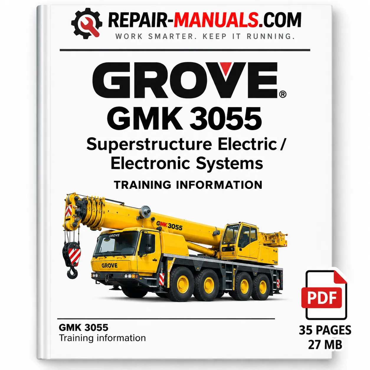
Description
GROVE GMK 3055 Superstructure Electric & Electronic Systems Training Manual
The GROVE GMK 3055 Superstructure Electric & Electronic Systems Training Manual is a technical training reference focused on the electrical and electronic control systems used on the GMK 3055 mobile crane. The manual explains the transition from conventional relay-based control systems to the ECOS electronic control architecture and provides an overview of the major control modules, communication networks, sensors, switches, and actuator systems.
Manual Specifications
| Specification | Details |
|---|---|
| Machine | GROVE GMK 3055 |
| Manual Type | Training Information / Technical Manual |
| Subject | Superstructure Electric & Electronic Systems |
| System | ECOS Electronic Control Operating System |
| Main Controllers | ESX Control Modules |
| Communication | CAN Bus / RS-232 |
| Contents | Electrical controls, CAN Bus, ESX, I/O boards, joysticks, switches, sensors, EKS 5, solenoids and technical diagrams |
| Total Pages | 35 Pages |
| File Size | 27 MB |
| Format | |
| Language | English |
Electronic Control System Overview
The manual introduces the ECOS (Electronic Control Operating System) and explains how modular, bus-based electronic control reduces wiring complexity while allowing high-speed communication between crane systems. It describes real-time communication between the hydraulic system, telescopic boom, EKS 5 light rated capacity indicator, carrier controls, and other electronic components.
The training information also explains the harsh operating environment requirements of the electronic controls, including operation across a temperature range of approximately -40°C to +85°C, electromagnetic compatibility, voltage overload protection, short-circuit protection, and integrated diagnostic capabilities.
CAN Bus System
A major section of the manual is dedicated to the Controller Area Network (CAN Bus). It covers CAN bus structure, communication principles, network topology, termination resistors, message identifiers, error detection, multi-master operation, and the relationship between the different crane control modules.
The manual explains the CAN bus hierarchy and provides diagrams showing how the ESX controllers, I/O boards, EKS 5 system, joysticks, handset, sensors, and carrier components communicate. The appendix includes a dedicated CAN bus components overview and CAN bus layout for the GMK 3055.
ESX Controller and Drive Units
The manual provides detailed training information on the ESX controller and drive units, including their purpose, features, diagnostic functions, input/output capabilities, memory, CAN interfaces, and PWM outputs.
The ESX block diagram illustrates connections for digital inputs, analogue inputs, PWM outputs, CAN interfaces, RS-232 communication, microcontroller functions, safety relay, system supervisor, and memory components. ESX module identity resistors and resistor boards are also covered, together with their locations and applications.
I/O Boards and Diagnostics
The manual explains how I/O boards are used as slaves to extend the available inputs and outputs of the ESX control modules. It identifies I/O board functions and provides connection information for components such as counterweight controls, turntable locking, telescope cylinder functions, cabin movement, and other crane functions.
A dedicated section explains I/O board configuration and LED functions. The five status LEDs are described, including indications for hardware reset, program operation, timeout, initialization, power supply condition, and CAN bus status.
Joysticks, Switches and Sensors
The crane control joystick section describes the two X/Y-axis control joysticks, their integrated switches and functions, CAN bus communication, deadman control, HDRI functions, horn operation, high-speed functions, and carrier steering controls. The manual also explains that joystick characteristics can be configured through the crane control display.
Proximity and digital switch sections cover counterweight switches, turntable proximity switches, telescope cylinder proximity switches, and digital switch inputs. The manual describes switch states, reference voltages, error detection, cable-break detection, short-to-battery conditions, and the associated ECOS diagnostic functions.
Analogue Inputs and Handset Control
The manual describes the ESX analogue inputs used for items such as sensor signals, pressure transducers, joystick inputs, wind-speed generators, and module identification. It also covers the remote handset used for rigging operations and emergency purposes when the superstructure cabin control system is unavailable.
Oil Cooler and EKS 5 Control
The oil cooler control section explains the electric air-blast oil cooler system, MOSFET switching control, hydraulic oil temperature sensing, and the relationship between the temperature sensor and ESX control system.
The EKS 5 light Rated Capacity Indicator section explains how rated-capacity and operating-limit information is integrated with ECOS. It describes CAN-based shutdown communication, safety relay functions, motion cut control, hoist limit functionality, and the interaction between the RCI, ESX modules, and crane control system.
Solenoid Locations and Technical Drawings
Detailed visual information is provided for turntable solenoid valve locations and telescope cylinder solenoids. The appendix contains additional technical drawings covering I/O board layout, the main hoist control principle, CAN bus components, and the complete CAN bus layout.
The diagrams throughout the manual make it particularly useful when studying the relationship between electronic controllers, switches, sensors, hydraulic control blocks, solenoid valves, and communication networks on the GMK 3055.
Manual Contents
- General description of GMK 3055 electronic systems
- Electrical relays and interface locations
- Relay board and proportional control switching
- CAN Bus principles and structure
- ESX controller and drive units
- ESX module hierarchy and CAN bus hierarchy
- ESX identity and resistor boards
- CAN termination resistors
- I/O boards and configuration
- I/O board LED diagnostics
- Crane control joysticks
- Proximity and digital switches
- Counterweight and telescope cylinder switches
- Analogue inputs
- Remote handset control
- Oil cooler control
- EKS 5 light Rated Capacity Indicator
- Turntable and telescope cylinder solenoid locations
- I/O board layout drawing
- Main hoist control principle
- CAN bus components overview
- GMK 3055 CAN bus layout
Reference: This product is based on the supplied GMK Crane CARE training document titled GMK 3055. Training Information: Super Electric/Electronic Systems. The document itself advises referring to the applicable electrical circuit diagrams and related ECOS documentation for complete system detail.




Reviews
There are no reviews yet.