Description
Caterpillar C11 & C13 Engines Electrical System (Schematic) Manual PDF Download
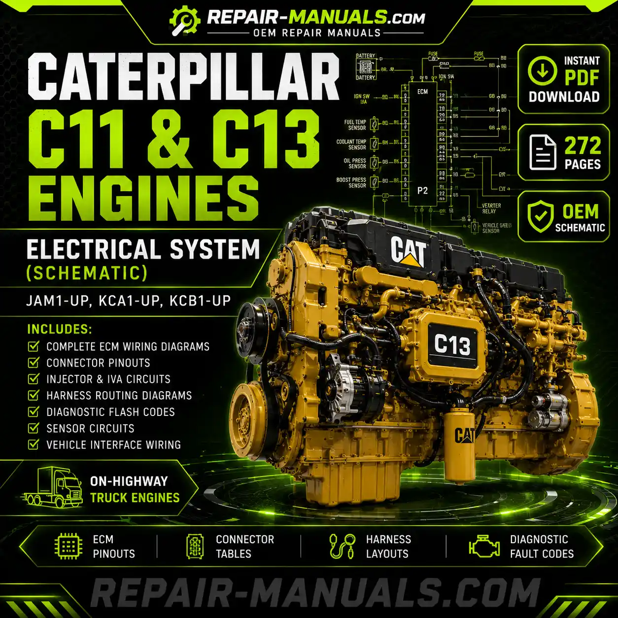
Download the official OEM Caterpillar C11 & C13 Engines Electrical System (Schematic) Manual in PDF format. This factory electrical schematic manual provides complete wiring information for diagnosing, testing, and repairing the electrical systems used on Caterpillar C11 and C13 On-Highway Truck Engines.
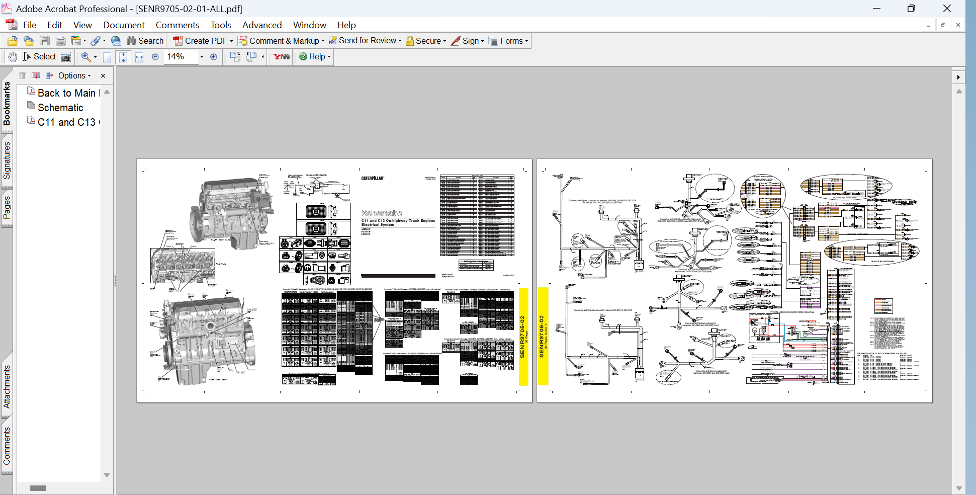
Designed specifically for professional technicians, fleet maintenance departments, and owner-operators, this manual contains detailed electrical schematics, ECM connector pinouts, harness routing diagrams, sensor wiring layouts, injector circuit information, and diagnostic flash code references required to troubleshoot complex electrical faults accurately.
“`html
Applicable Engine Serial Number Prefixes
- JAM1-UP
- KCA1-UP
- KCB1-UP
What’s Included in This Manual?
This OEM Caterpillar schematic manual contains complete electrical system information used to identify, diagnose, and repair engine-related electrical problems.
- Complete Engine Electrical Schematics
- ECM Connector P1 & P2 Pin Assignments
- Engine Control Module (ECM) Wiring Diagrams
- Harness Identification Charts
- Wire Color and Circuit Identification
- Connector Reference Tables
- Harness Routing Layouts
- Connector and Splice Location Diagrams
- Twisted Pair Circuit Identification
- Battery and Ground Circuit Information
- Starting Circuit Diagrams
- Sensor Power Supply Circuits
- Data Link Communication Circuits
- Vehicle Interface Wiring Diagrams
- Cab Harness Recommendations
Sensor Wiring Coverage
The manual provides complete wiring diagrams and connector details for engine sensors used throughout the Caterpillar electronic engine control system.
- Boost Pressure Sensor
- Atmospheric Pressure Sensor
- Engine Oil Pressure Sensor
- Engine Coolant Temperature Sensor
- Fuel Temperature Sensor
- Intake Manifold Air Temperature Sensor
- Primary Engine Speed/Timing Sensor (Crankshaft)
- Secondary Engine Speed/Timing Sensor (Camshaft)
- Intake Valve Actuation Pressure Sensor
- Accelerator Pedal Position Sensor
- Coolant Level Sensor Circuits
- Vehicle Speed Sensor Circuits
Injector and Intake Valve Actuation (IVA) Coverage
This manual includes detailed wiring information for the complete injector and IVA system used on Caterpillar C11 and C13 engines.
- Injector Circuits 1 through 6
- Injector Harness Connector Identification
- Front Valve Cover Connector Schematics
- Rear Valve Cover Connector Schematics
- Intake Valve Actuator Circuits 1 through 6
- Intake Valve Actuation Pressure Solenoid Circuits
- Intake Valve Actuation Pressure Sensor Circuits
- Retarder Solenoid Wiring Diagrams
- Engine Coolant Diverter Solenoid Circuits
Harnesses Covered
The schematic manual provides connector tables and wiring layouts for multiple Caterpillar engine harness configurations, including retarder and non-retarder applications.
- 234-9512
- 238-4778
- 240-6655
- 246-4346
- 267-1274
- 243-2302
- 243-2315
- 266-7689
- 239-5523
- 239-5524
- 240-9996
- 240-9997
- 249-0093
- 249-8681
- 253-7501
- 253-7503
- 238-9662
- 238-9663
Diagnostic Flash Code Reference
One of the most valuable features of this manual is the integrated Caterpillar diagnostic flash code listing used during troubleshooting procedures.
Diagnostic coverage includes:
- Injector Circuit Fault Codes
- Engine Overspeed Warnings
- Coolant Temperature Faults
- Coolant Level Warnings
- Oil Pressure Faults
- Fuel Temperature Faults
- Intake Air Temperature Faults
- Atmospheric Pressure Faults
- Brake Pedal Switch Faults
- Vehicle Speed Signal Faults
- ECM Battery Voltage Faults
- J1939 Data Link Communication Faults
- J1587 Communication Faults
- Retarder Circuit Faults
- Theft Deterrent Faults
- Intake Valve Actuation System Faults
- Intake Valve Actuator Faults
- Sensor Supply Voltage Faults
Vehicle Interface Wiring
The manual also contains recommended vehicle wiring diagrams illustrating connections between the Caterpillar ECM and truck chassis systems.
- Cruise Control Switches
- Accelerator Pedal Position Sensors
- Brake Pedal Switches
- Clutch Switches
- Tachometer Outputs
- Speedometer Outputs
- Warning Lamp Circuits
- Check Engine Lamp Circuits
- J1939 Data Link Connections
- J1587 Data Link Connections
- Battery Power Distribution
- Starter and Alternator Circuits
Who Should Use This Manual?
- Caterpillar Diesel Technicians
- Fleet Maintenance Managers
- Heavy Truck Electrical Specialists
- Owner Operators
- Independent Repair Shops
- Mobile Service Technicians
- Engine Rebuilders
This official Caterpillar schematic manual is an indispensable troubleshooting resource, combining complete electrical diagrams, connector information, harness layouts, and diagnostic references into one comprehensive publication. Whether diagnosing sensor faults, repairing injector circuits, tracing harness issues, or verifying ECM inputs and outputs, this manual provides the accurate factory information needed to complete the job correctly.



Reviews
There are no reviews yet.