Description
Hitachi 4HK1 & 6HK1 Engine Service Manual
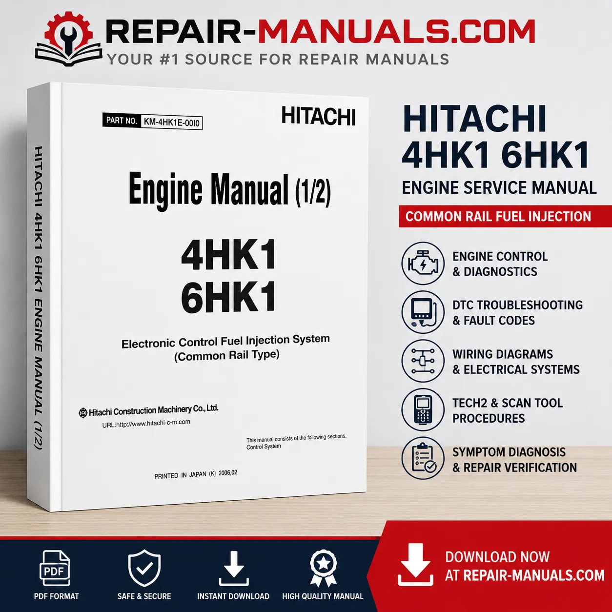
This comprehensive Hitachi 4HK1 & 6HK1 Engine Service Manual is designed to assist with professional engine service, electronic control diagnosis, troubleshooting, and repair. The sample manual identifies the document as an engine manual covering the 4HK1 and 6HK1 engines and provides detailed information on the electronic control fuel injection system using common rail technology.
The manual explains the structure and troubleshooting procedures of the engine electronic control system and emphasizes the importance of following a systematic diagnostic process. It covers diagnostic procedures from customer complaint confirmation and visual inspection through DTC diagnosis, symptom-based troubleshooting, repair confirmation, and final checks.
Manual Specifications
| Manual Type | Engine Service / Repair Manual |
| Manufacturer | Hitachi Construction Machinery |
| Engine Models | 4HK1 & 6HK1 |
| System Covered | Electronic Control Fuel Injection System – Common Rail Type |
| Manual Contents | Engine control, diagnostics, DTCs, wiring, scan tools, Tech2, troubleshooting and repair verification |
| Format | Digital PDF Manual |
| Total Pages | 958 Pages |
| Download Size | 30 MB |
| Language | English |
| Use | Service, Repair, Troubleshooting & Diagnostics |
Electronic Common Rail Fuel Injection System
The manual provides extensive information about the electronic control fuel injection system, including the Engine Control Module (ECM), sensors, actuators, common rail pressure control, suction control valve (SCV), fuel temperature sensing, engine coolant temperature sensing, crankshaft and camshaft position sensing, EGR control, and related electrical circuits.
It also explains wiring colors, wiring diagrams, connector information, engine harness locations, system circuits, and the relationship between the engine control module and machine control systems.
Diagnostic Trouble Codes and Troubleshooting
A major section of the manual is dedicated to Diagnostic Trouble Codes (DTCs). The sample contents include fault diagnosis for common rail pressure faults, injector circuits, crankshaft and camshaft sensors, boost pressure sensors, coolant and fuel temperature sensors, EGR systems, engine oil pressure sensors, ECM faults, power supply faults, CAN communication faults, and other electronic control problems.
The manual also includes symptom-based troubleshooting for conditions such as engine starting problems, engine stalling, hunting or rough idling, engine output shortage, excessive white smoke, excessive black smoke, abnormal noise, and deteriorated fuel or oil consumption.
Tech2 and Scan Tool Procedures
Detailed diagnostic tool information is included. The manual explains the use of Tech2 and other scan tools for reading DTCs, viewing engine data, performing actuator tests, recording snapshots, reviewing captured data, plotting diagnostic parameters, and carrying out programming-related procedures.
The Tech2 section describes the unit components, display functions, power supply, DLC connection, PCMCIA card handling, startup procedures, diagnostic menus, DTC display and clearing, Data Display, Snapshot functions, and graph/plot functions.
Diagnostic Procedures
The troubleshooting methodology includes confirming the customer’s complaint, performing a pre-inspection, checking service information, investigating DTCs, and carrying out symptom-based diagnosis when no applicable DTC is available. The manual also discusses history faults, present faults, intermittent faults, and procedures for confirming repairs after corrective work.
Wiring Diagrams and Electrical Diagnosis
Electrical diagnosis information includes wiring color codes, wiring diagram interpretation, engine harness identification, connectors, communication circuits, sensor circuits, actuator circuits, and ECM-related systems. The sample pages also contain detailed circuit diagrams illustrating the connections between the ECM, sensors, machine control unit, diagnostic equipment, and engine components.
Service and Safety Information
The manual includes important service precautions relating to electronic components, electrostatic discharge, welding work, electrical equipment, fuel system components, and diagnostic equipment. It specifically discusses precautions when handling ECM components and high-pressure fuel system parts.
The sample also explains that high-pressure fuel and injector pipes should not be reused after removal and provides precautions concerning common rail components.
Repair Verification
After repair, the manual recommends confirming DTC status, clearing stored codes, checking scan tool data, verifying stable engine operation, and confirming restarting performance. These procedures help ensure that the original fault has been properly corrected before the machine is returned to service.
Manual Contents Include
- 4HK1 and 6HK1 engine information
- Electronic control fuel injection system
- Common rail fuel system diagnosis
- Engine Control Module (ECM)
- Engine component location information
- Wiring diagrams and wiring color codes
- Engine harness and connector information
- Diagnostic Trouble Codes (DTCs)
- Fault and symptom troubleshooting
- Scan tool diagnostic procedures
- Tech2 operation and diagnostic functions
- Data Display and Snapshot functions
- Actuator testing
- OBD system checks
- Starting, fuel, intake and exhaust system checks
- EGR and QOS system checks
- Repair confirmation procedures
- Programming and ECM-related procedures
Reference: The supplied sample identifies the manual as an engine manual for the 4HK1 and 6HK1 engines and documents the electronic control fuel injection system (common rail type), including diagnostic procedures, wiring information, DTCs, Tech2 operation, and symptom troubleshooting. :contentReference[oaicite:0]{index=0}



Reviews
There are no reviews yet.