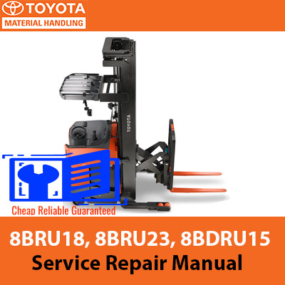
Package Include
Toyota 8BRU18, 8BRU23, 8BDRU15 Reach Lift Truck Service Repair Manual
Language
English
Format
PDF
Total Number of pages
340
Publication Number
00700-CL220-08, Issued: 23 Jan 2009
Compatible
All windows and mac systems
Additional Requirement
User needs to Install PDF Reader Software
Shipping Policy
Download link by high speed web server Total Download size 17 mb
Overview
With This Original Factory Service Repair Manual The Technician can Find and Solve any problems encountered in the operation of your Toyota Reach Lift Truck Models of :
Toyota 8BRU18, 8BRU23, 8BDRU15 Reach Lift Truck
24 Volt Models – Serial No. 24,000 and Up
36 Volt Models – Serial No. 36,000 and Up
DOWNLOAD SAMPLE OF THIS PDF MANUAL
The Factory was highly recommended use this manual for Technicians before you touch your Toyota Machine
This manual contains original instructions, verified by the manufacturer (or their authorized representative)
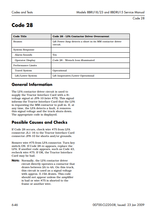
This Original factory pdf manual and pdf service Manual very clear and it is 100% printable version, contains with high quality images and circuit diagrams
Enhance the longevity and performance of your Toyota 8BRU18, 8BRU23, and 8BDRU15 Reach Lift Trucks with our comprehensive Service Repair Manual. This essential guide provides detailed instructions, diagrams, and troubleshooting tips to ensure efficient maintenance and repair. With clear, step-by-step procedures, you can confidently tackle any service task, minimizing downtime and maximizing productivity. Invest in this manual to keep your equipment running smoothly and efficiently for years to come
Contents of this pdf service manual
How to Use This Manual
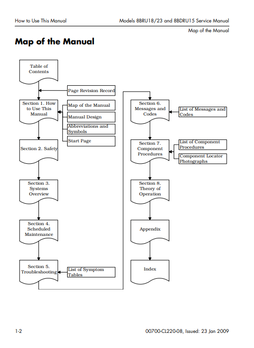
Map of the Manual
Manual Design
Abbreviations and Symbols
Safety
Definitions
General Safety
Battery Safety
Static Precautions
Jacking Safety
Tie-down for Transport
Welding Safety
Systems Overview
Vehicle Specifications
General System Data
Modes of Operation
Definitions
Planned Maintenance
Planned Maintenance Guidelines
Initial 90 Day/250 Deadman Hour (HD) Maintenance
Every 180 days or 500 Deadman Hours (HD)
Every 360 Days or 2000 Deadman Hours (HD)
Lift Chain Inspection
Fork Inspection
Troubleshooting
Electrical Troubleshooting
Hydraulic Troubleshooting
Symptom Tables
Codes and Tests
Modes of Operation
Operator’s Display
Self-Diagnosis Mode
Passwords
Disable Brush Wear Indicator (DC lift only)
Start the Hour Meter
Analyzer (AnL) Mode
Calibrate (Calibrte) Mode
Configure (Configur) Mode
Tuning Mode
Code Summary List
Component Procedures
List of Component Procedures
Component Locator Photos
Frame and Accessories
Panels and Covers
Decals
Steering and Controls
Steer Motor
Steer Controller
Control Handle
Traction and Braking
Deadman Pedal Assembly
Caster Assembly
Caster Springs and Stops
Brake
Drive Wheel
Drive Unit
Electrical
Battery Procedures
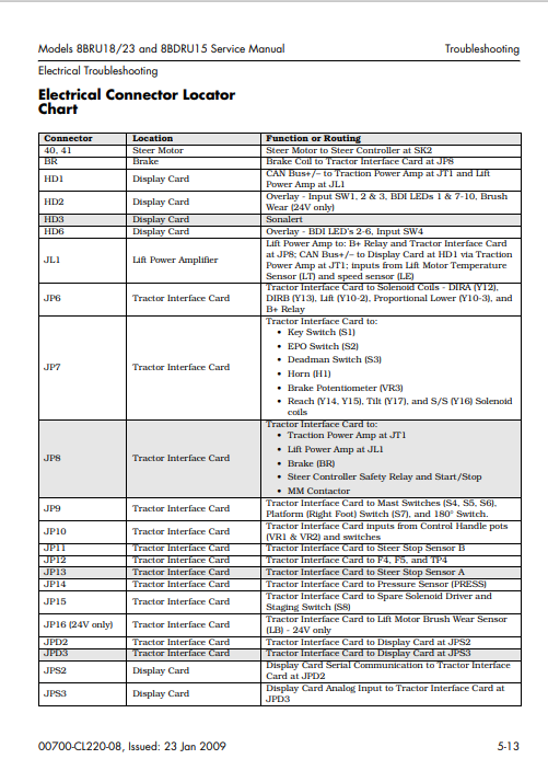
Wiring and Harness Connectors
Contactors
Switches (General)
Key Switch (S1)
EPO Switch (S2)
Lift Inhibit Switch (S4)
Mast Switch 1 (S6)
Deadman (Left Foot) Switch (S3)
Platform (Right Foot) Switch (S7)
Staging Switch (S8)
180° Switch
Steer Stop Sensors
Horn
Motors
Traction Motor
Power Amplifiers
Height Indicator (optional)
Hydraulics
Hydraulic Fluid
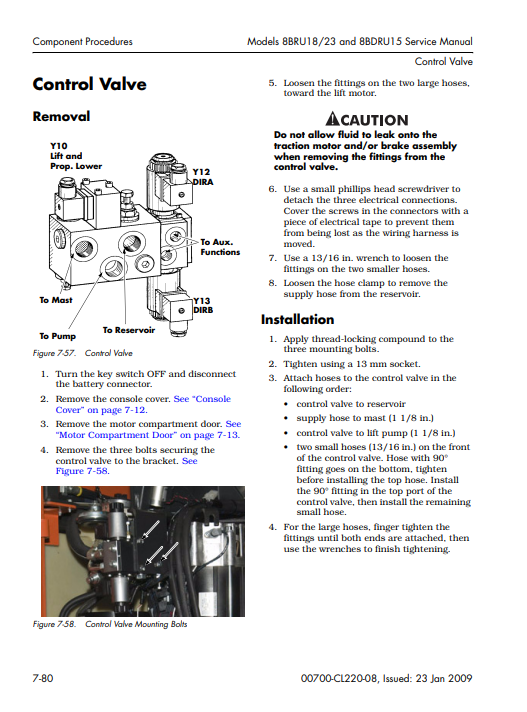
Control Valve
Reach/Tilt/Sideshift Manifold
Solenoids
Free Lift Cylinder Repair
Staging Cylinder Repair
Tilt Cylinder (single cylinder carriage)
Tilt Cylinder (dual cylinder carriage)
Reach Cylinder
Velocity Fuses
Mast
Mast Roller Bearings
Lift Chains
Free Lift Chain Anchors
Staging Chain Anchors
Over-the-Mast Hose/Cable
Reach Carriage Assembly
Theory of Operation
Electrical Functions
Braking System
Steering System
Traction System
Lift/Lower System
Auxiliary Hydraulic Functions
Indicators and Switches
