Description
New Holland B95C Backhoe Loader Electrical Diagrams PDF Manual
The New Holland B95C Backhoe Loader Electrical Diagrams manual is an essential troubleshooting resource for diagnosing and repairing electrical faults throughout the machine. Developed using OEM schematic information, this manual provides technicians with clear circuit layouts and connector references for efficient electrical repairs.
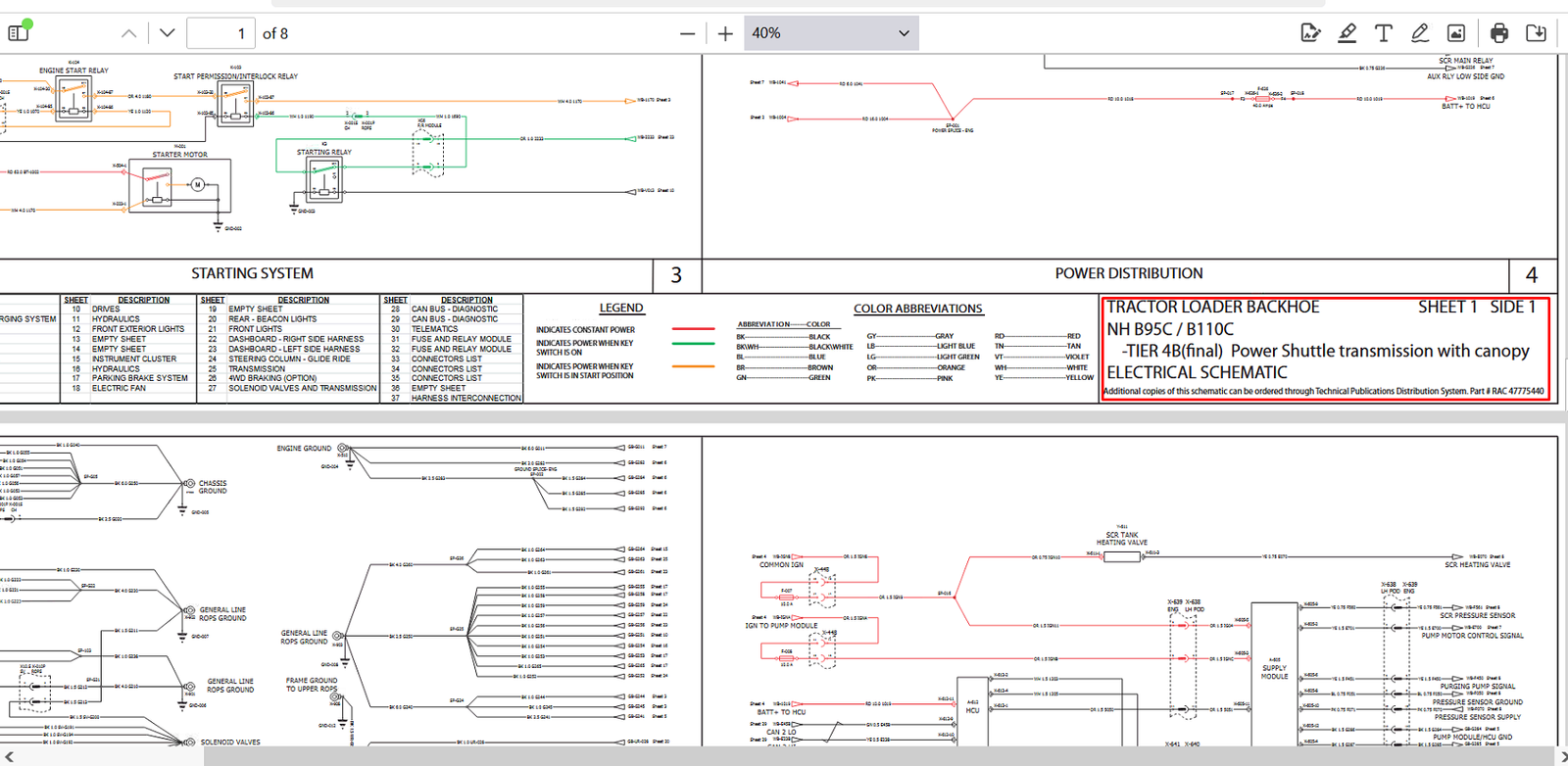
The diagrams cover major machine electrical circuits including power distribution, starting and charging systems, engine management, lighting, transmission controls, fuse and relay modules, CAN bus diagnostics, telematics, connector identification, and harness interconnections. Clear wiring paths, connector references, component locations, fuse ratings, relay layouts, and color-coded circuits help reduce troubleshooting time and improve repair accuracy.
The supplied electrical diagrams cover the Tier 4B (Final) Power Shuttle transmission configuration and include comprehensive wiring information for major machine systems.
| 📘 Product Type | Electrical Diagrams Manual |
| 🏷 Product Title | New Holland B95C Backhoe Loader Electrical Diagrams |
| 📄 Publication Number | RAC 47775440 |
| 🚜 Applicable Models | New Holland B95C Backhoe Loader |
| ⚙ Configuration | Tier 4B (Final) Power Shuttle Transmission with Canopy |
| 🌐 Language | English |
| 💾 Format | |
| 📑 Pages | 8 |
| 📦 File Size | 10 MB |
| 🔍 Searchable | Yes |
| 🖨 Printable | Yes |
| 💻 Compatible Devices | PC, Mac, Tablet & Smartphone |
| ⚡ Delivery | Instant Digital Download |
| ♾ Download Access | Lifetime Access |
Electrical Systems Covered
- Power Distribution and Charging System
- Starting System
- Grounding Circuits
- Denox / ECU Supply Module
- Engine Control System
- Drive Controls
- Hydraulic Electrical Components
- Front Exterior Lighting Circuits
- Instrument Cluster
- Parking Brake System
- Electric Fan System
- Rear Beacon and Work Lights
- Front Lighting System
- Dashboard Harnesses (Left and Right)
- Steering Column and Glide Ride Controls
- Transmission Electrical Circuits
- 4WD Braking Circuits (Optional)
- Solenoid Valves and Transmission Controls
- CAN Bus Diagnostic Networks
- Telematics System
- Fuse and Relay Modules
- Connector Identification Lists
- Harness Interconnection Diagrams
Manual Features
- OEM-quality wiring diagrams and electrical schematics.
- Color-coded wire identification and abbreviations.
- Fuse and relay module layouts with component references.
- Detailed connector identification tables.
- Harness routing and interconnection illustrations.
- CAN Bus diagnostic information for advanced troubleshooting.
- Searchable PDF format for quick navigation.
- Printable pages suitable for workshop use.
Why This Manual Is Valuable
Electrical problems can be difficult and time-consuming to diagnose without accurate diagrams. This manual enables technicians to trace circuits confidently, locate connectors quickly, identify fuse and relay assignments, and perform repairs according to factory specifications.
Whether you are troubleshooting lighting faults, engine management issues, starting problems, transmission controls, or communication network errors, this manual provides the electrical information required to complete the job correctly.
According to the OEM schematic index, the manual includes extensive coverage of engine controls, CAN diagnostics, telematics, fuse modules, connector lists, and harness interconnections.


Reviews
There are no reviews yet.